Many people know the where the mass air flow sensor it, they know it reads mass air flow, but what does this sensor actually do and why is it so critical? It’s a very useful invention, but at the same time it is very sensitive to change, and a faulty or one that is incorrectly setup will cause you issues. Many people do not know, simply fitting an air filter or a different induction kit to a car could be doing much more than they think, improvements felt may not just be the air filter alone, but incorrect and potentially dangerous running of the engine due to MAF errors.
Ever been to a Dyno Day and seen a car running mysteriously lean? In many cases it may just be down to errors in the MAF reading. This article will explain what the sensor does, and why it can make such a huge difference to the running of the car.
Well the job of this sensor is to measure the amount of air mass being digested by the engine. The critical word being air in MASS which is expressed in a mass over time, for example (Kg/Hr) Kilograms per Hour or Grams per Second (g/s).
If you know the mass of the air then you know mass of the fuel you require to add to maintain your desired air fuel ratio. However, if you read this amount of air wrong then you will add the wrong amount of fuel. This will cause an engine to run rich or lean.
Older systems used to work out the air mass mathematically by knowing the size of the engine, the pressure and temperature of the air as well as the amount of oxygen in a typical mass of air. But this required a lot more calculations and a lot more sensors to achieve. The formula used was the ideal gas law which is as follows.
n = PV / RT
n = Air Mass in moles.
P = Absolute Pressure of the air.
T = Absolute Temperature of the air.
V = The volume or size of the space you’re putting the air in.
R = The gas constant for atmospheric air.
If you changed anything about the car, such as put a different set of cams in or changed your exhaust manifold or anything that might change how the engine breaths all this maths would have been made invalid as not all the air calculated by this formula would make it inside the cylinder and a table known as the Volumetric Efficiency Table would be used which is simply what percentage of the air actually made it all the way into the engines cylinders.
Skip forward to more modern times you’ll find that we’ve developed sensors which can do all of this in one go without the need for any maths, the Mass Air Flow sensor. This works out the exact air mass coming into the engine regardless what conditions, whether it’s a hot day or a cold day, whether you’re up a mountain in low pressure or down at sea level in higher pressure.
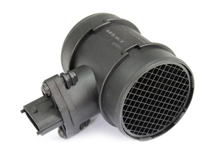
The sensor sits in the intake tract just after the air filter and produces a signal from 0V to 5. This works by having a small element of wire which is heated and the atoms hitting it cool it down. The more atoms hit it, the higher the output voltage back to the ECU. If your engines volumetric efficiency changes, then it’s not a problem the additional air mass or reduction in air mass is detected by the sensor and fuel is calculated correctly.
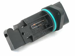
But there is a major catch to the sensor, if you do anything to the position of the sensor in your intake or its surrounding pipe work then you will change the accuracy of the sensor. This is because the sensor is a small element in the middle of the air stream from one edge of the housing to the centre. If the pipe work either side is not perfectly straight but infact curved then more of the air will move around one side than another. For example if you take the Astra VXR cross over it has a 90 degree bend on either side and this bend is taken into account when the original MAF calibration was written. If you take the bends away by fitting a short intake pipe and using a cone or a CDTI box then the calibration will be incorrect. But even just rotating the sensor to a different angle will change how the air flows through the MAF sensor, if it was flowing more to one side it and the sensor was in the main air flow or would then be on the side with a lesser air flow which again would cause it to read wrong and in this case read low and cause lean running.
There is also a limit to how much air the sensor can read before the cooling effect will prevent the wire from heating up at all to get a lower voltage then its maximum 5V output. This is known as clipping where the sensor will report the same air flow even when the cars air flow is increasing beyond this. This is the time where you need to upgrade the MAF sensor to a larger one, by doing so you will have more air missing the sensor and that means the total amount of air flow supported by the sensor before it maxes out is higher.
Here is the calibration curves of various sensors ranging from 70mm, 80mm to 90mm. The power the sensors support range from around 250BHP to 500BHP. The left axis shows the Kg/Hr and the bottom axis shows the voltage output. This calibration curve must be properly inserted in to your ECU map to match the sensor you’re running. Incorrectly doing so is potentially dangerous to your engine, and will cause serious running issues or may even fail to start.
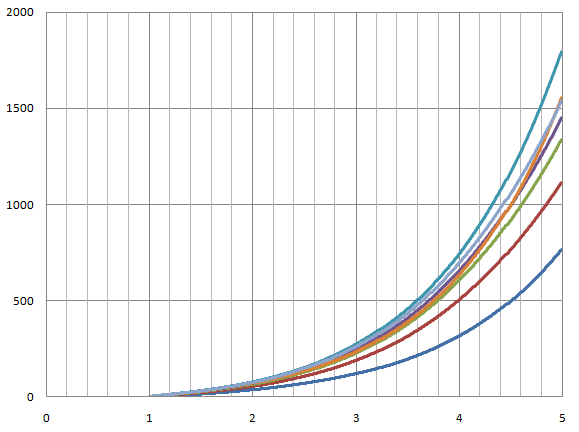
The blue line is an Astra GSi 70mm, the red is the Astra VXR 80mm, and the rest are a number of 90mm MAF solutions available. As you can see despite there being several 90mm options each one has different air flow amounts depending on different intakes used with them. So as you can see, the wrong air mass reading will give the wrong fuel requirement and therefore you could run leaner or richer than the map requires.
By knowing how much air mass a cylinder can hold you can take the total air mass reading, divide it by the number of cylinders and using the engine speed work out how many cylinder fills are happening in a certain time period you can then know how many atoms of air make it into each cylinder this is how you determine how much fuel is needed. But that is just the start, the MAF is also used to determine engine load. If you know how big the cylinder is you can work out how much air the cylinder can hold. If you have an engine at half throttle the cylinder might be getting 40% of the maximum air it could take. This is 40% load. If you then went full throttle you will find the cylinder load will go up to around 90-105% depending on the engines efficiency. But if you then add a turbo you might find you’re forcing way more air in then could naturally occur. At low boost you might say this is 130% load, or and higher boost perhaps 180% load. A typical Astra VXR stage map will fill the cylinder at around 170-200% depending on the boost levels.
But why is this load important? Because so many other ECU functions are using this load amount of pick up how they will run. Everything from spark advance, to the boost required, to the traction control system will use this load value. If you’re reading air mass wrong, you’re reading load wrong. Hence cars might have odd flat spots, or perhaps run into Knock where it shouldn’t or even throttle closures or boost spikes and dips.
What makes properly custom mapped cars so good to drive and so quick over generic mapped cars is quite often 50% or more down to just re calibrating the MAF sensor to the cars particular air intake system. Correcting the air flow reading will stop all fueling issues and will make the car fuel perfect. It will remove any hesitation and flat spots caused by the wrong spark angles and give perfect boost response as the engine load is being properly determined.
Some other MAF sensor issues caused by altering the car include restricting the air intake before the MAF. Some people do not modify the airbox when fitting the CDTI kit onto a car running the 80mm MAF. Because the box comes from a car that runs 70mm pipes it only has a 70mm outlet. This channels the air through the centre of the MAF and upsets its readings. It’s extremely important that you buy a kit already modified to 80mm if you need to use it on a car running an 80mm MAF, or you modify the box yourself.
Dump valves also wreck havoc to your MAF readings, the air that was metered by the MAF gets ejected without knowledge of the ECU to atmosphere. This means the can runs rich after a gear change and the car see’s this on the lambda sensors and pulls a fuel trim. But by then air flow is returning to normal which will then cause a moment of lean running as the fuel trim is reversed.
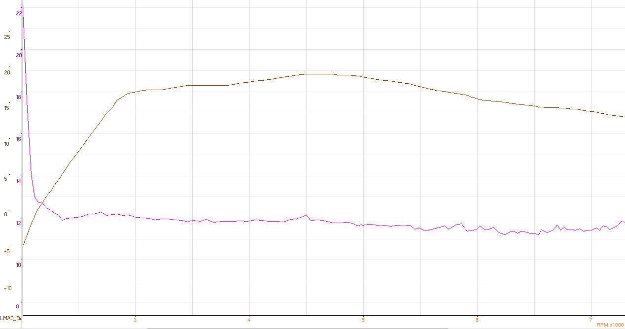
Here is a video of a car that was running with a generic flash map but then put on an open cone filter. The car lost a lot of power and you can clearly see the air fuel ratios run dangerously lean.
https://www.youtube.com/watch?v=Km-mR6Tgw1Q